Displacement and Acceleration
Arrays of satellites cannot maintain a constant displacement above or below the orbital plane without a constant (and significant) acceleration keeping them there. The ΔV needed over the lifetime of a satellite is beyond the range of high Isp engines. Further, it is unnecessary; by using constellations that evolve and rotate in three dimensions along the orbit, the same results (high gain main lobe, suppressed sidelobes) can be achieved. It is important to work with orbital mechanics, not fight nature and physics.
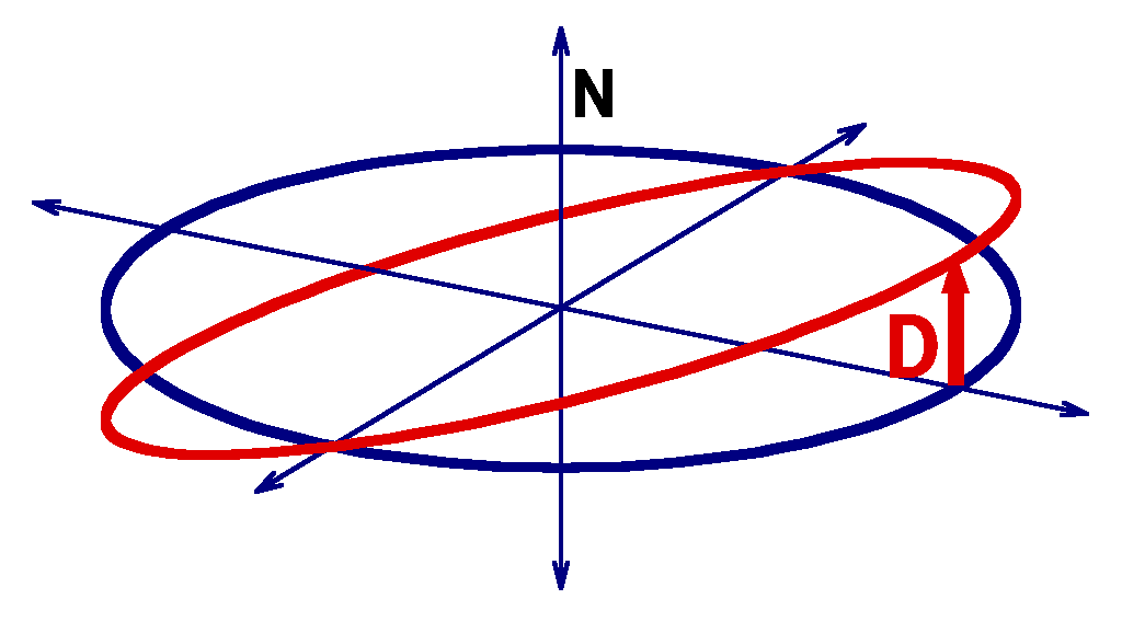
Imagine an attempt to permanently "hover" on the "north" side of a circular equatorial orbit. All Kepler earth orbits are mapped onto planes which intersect the center of the earth, and our hovering object is actually on a different, slightly inclined orbit. If the object is free to follow the orbital mechanics without an external force, it will follow a slightly different inclination circular orbit that intersects the original orbital plane.

If the displacement of the unconstrained orbit differs from the equatorial orbit by d = D \sin{ \omega t } , then the acceleration is a = - \omega^2 D \sin{ \omega t } . Since \omega^2 = \mu / R^3 for a circular orbit without the J_2 perturbation, the peak acceleration is \mu D / R^3 . For μ = 398600.44 km3/s2, the acceleration at maximum displacement is given for various altitudes in the table below, as well as the accumulated \Delta V over a 10 year mission:
|
per meter of displacement D |
|||
Altitude |
Radius |
Acceleration |
10 year \Delta V |
|
km |
km |
μm/s2 |
m/s |
|
200 |
6578 |
1.400 |
441.9 |
|
600 |
6978 |
1.173 |
370.2 |
|
1000 |
7378 |
0.992 |
313.2 |
|
2000 |
8378 |
0.678 |
213.9 |
|
6411 |
12789 |
0.191 |
60.1 |
m288 |
35786 |
42164 |
0.0053 |
1.67 |
GEO |
These numbers are multiplied by the displacement; a 13 meter displacement at 600km altitude requires 4812 m/s \Delta V over 10 years. Even with a high efficiency VASIMR engine, the vehicle could be entirely fuel tanks, solar cells, and radiators, and have a hard time making that much \Delta V over a decade. And you can't do a north-south hover with electrodynamic tethers or Lorenz forces; both work across magnetic field lines, not along them.
Alternatives to Continuous Displacements
Though it is more complicated to think about, it is a lot easier to deploy three dimensional arrays that naturally rotate and evolve as they orbit. 90° right angles do not stay right angles in these arrays, but relative positions can be very precise and predictable, with only infinitesimal corrections for J_2 effects and somewhat larger corrections for light pressure. Indeed, by modulating the light pressure with electrochomic panels, you can keep an array predictably positioned within fractions of a micron. The array evolutions will complicate the analysis, but an orbiting array turns at about a picoradian per microsecond, so the array has plenty of time to retarget communication beams and perform position tweaks. The main principle: Work with nature, and exploit its behavior, do not attempt to fight nature.
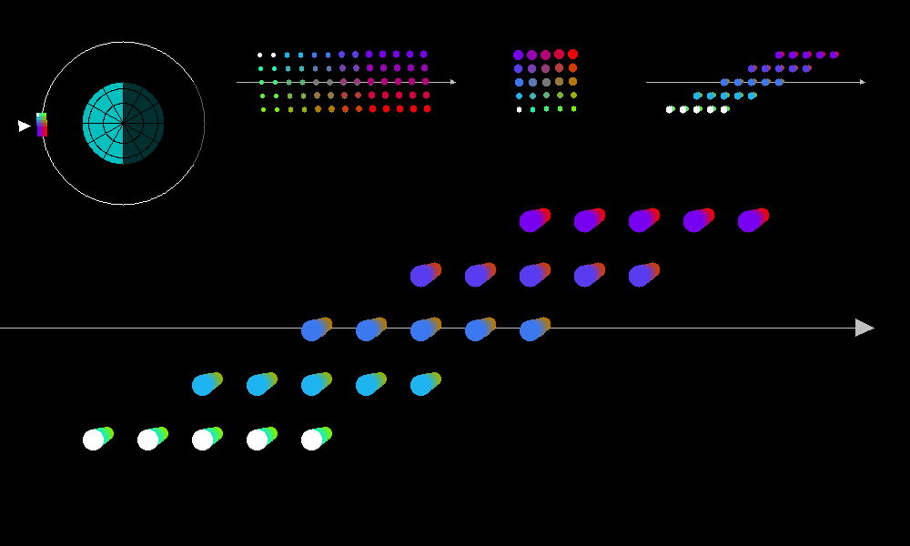
While there are many ways for arrays to rotate, it is easiest to pick a uniform mapping on a torus. We need to slightly change eccentricity if individual objects are spaced apart as they rotate through the main orbital plane, and an eccentric orbit compared to a circular orbit will skew forwards and back in the orbital direction:

With this in mind, we can map slightly inclined, slightly elliptic orbits onto a torus around a central circular orbit. In general, we can also map an eccentric "torus" around a central elliptic orbit, necessary to accommodate light pressure. The objects in this orbit will skew forwards and backwards as the array rotates, once per orbit:

ap02.c source
Click here for higher resolution.
Think of the colored dots as representing a cartesian grid, rotated and skewed towards apogee.
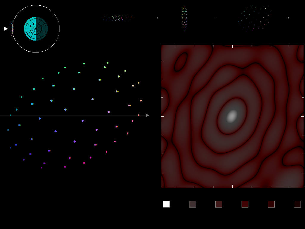
We can map more than a "cubic" array on this grid, for example, we can arrange our objects as a geodesic sphere mapped onto this apogee-skewed grid:

gsr03.c source
gsr03 linux binary - not sure about dependencies
Click here for higher resolution.
- The size of the orbiting array in the upper left (relative to earth and the orbit) is extremely exaggerated.
- flattening the array in the radial direction reduces apogee skew, but reduces sunlight at the 6 oclock positions in orbit.
- Someday, draw the view from the sun, estimating illumination
- There may be something wrong with the radio energy plot, I would expect it to skew to upper left for an array skewed to the upper right.
A "real" array will have 8,000 or more thinsats, perhaps as many as millions. These semi-symmetric, elliptical arrays generate amplitude patterns that vaguely resemble a sin(R)/R radial dropoff. However, a more complete (and numerically challenging) analysis will be needed to look for distant grating lobes. Not too distant, fortunately. Because thinsats are themselves covered with an array of slot emitters, they will beamform within about 3 degrees, so we need "merely" to look at a 1000x1000 kilometer patch for grating lobes. Also, keep in mind that wide bandwidth pulses will be smeared radially.
These are all uniform emitters making an Airy-disk-like pattern; we can probably change the weighting of edges to centers and generate a Gaussian taper. Indeed, we can dynamically change weightings in order to place nulls over nearby receivers that we do not want to interfere with.
This animation is 9% of the minimum sized "real" array.

gsr02.c source - array is stretched in the x (orbital) direction
gsr02 linux binary - not sure about dependencies
Click here for higher resolution.
This animation takes 4 hours to compute on one core of a 3GHz Pentium using double precision math. 99% of the work is a small, tight loop with a sin() and a cos() in it. It would go a LOT faster on the numeric array processor of an nVidia video card. Anybody want to learn CUDA?