Infrared Bandpass Filtered Thinsats
Thermal infrared filtering the front side of a thinsat reduces mass by half.
|
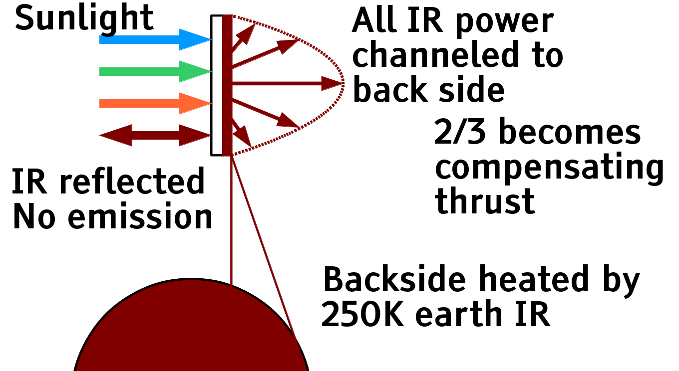
Adding an optical high-pass filter to the front (sunwards) side of a thinsat allows almost all the high energy sunlight to reach the solar cells, while pushing all the black body thermal emissions to the back side. The infrared emissions create light pressure thrust that balances 2/3 of the front side thrust, reducing orbit-distorting light sail thrust to 1/3 of the thrust caused by light absorption on the solar cells in front. |
Backside Infrared Thrust
Solid angle is the two dimensional "angular area" of something projected onto a unit sphere. The solid angle of a sphere is 4π steradians, the solid angle of a half-sphere is 2π steradians, the solid angle of a 1 degree wide band around any circumference of the sphere is 4π sin( 0.5° ) ≅ 0.1097 ster . A 1° radius circle is 9.570E-4 ster, and the visual size of the earth seen from the m288 orbit, close to 30° radius, is 2π( 1-cos(30°) ) ≅ 0.8418 ster.
Black body radiation from a flat surface is Lambertian - the intensity of the radiation per solid angle observed is constant. Perpendicular to the surface, a disk appears round with maximum solid angle. At angle \theta from perpendicular, the disk appears just as "bright" but the disk appears elliptical; just as bright per solid angle, but the solid angle size is smaller. Lambertian radiation means the intensity of the solid angle is the same, it just looks smaller so less radiation comes at you as the angle increases, dropping to zero edge-on. The radiation intensity at angle \theta is I_0 \cos( \theta ) where I_0 is a constant we shall calculate now.
For a thin band with an angle of \theta and width d\theta, the solid angle receiving the radiation is 2 \pi \sin( \theta ) d\theta and the radiation received is 2 \pi I_0 \cos( \theta ) \sin( \theta ) d\theta , or \pi I_0 \cos( 2 \theta ) d\theta . The total power P is the integral of this for \theta between 0 and \pi/2, so P = \pi I_0 or I_0 = P/\pi .
The light pressure thrust is proportional to power divided by the speed of light c . Perpendicular emissions create a perpendicular thrust, thrust at right angles to the perpendicular creates zero perpendicular thrust, and thrust at angle \theta from the perpendicular creates \cos( \theta ) times the perpendicular thrust. The perpendicular thrust from the band an angle of \theta and width d\theta is dF = ( 2 \pi I_0 / c ) \cos( \theta )^2 \sin( \theta ) d\theta = ( 2 P / c ) \cos( \theta )^2 \sin( \theta ) d\theta . Again integrating for \theta between 0 and \pi/2, the total force F = 2P/3 c , 2/3 of the light pressure thrust if the thermal radiation all came perpendicularly out the back. While it would be nice to beam ALL the thrust backwards captured by the front, summing to a total thrust of zero, that is not thermodynamically possible. Reducing the sum of frontside and backside thrust to 1/3, and reducing launch mass in proportion, is still Very Nice.
Note to perpetual motion machinists: A beam of light has a property called Etendue (ay-tahn-doo), a measure of the disorganization of the beam. Perfectly collimated light has an etendue of zero, all the rays are parallel. Disorganized light leaves a surface with rays scattering in all directions, and has higher etendue. No combination of mirrors and lenses can reduce etendue of the whole beam, the quantity always increases. Black body radiation has maximum etendue; there's no way to focus it on a spot smaller than the emitting surface. If you could, that spot could be hotter than the source, violating the second law of thermodynamics.
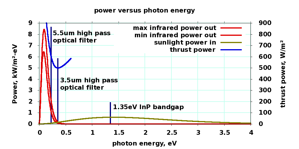
Front side absorption and thrust versus IR filter energy cutoff
W/m² |
|
|
1366 |
sun power |
|
1347 |
emitted power |
|
1347 |
absorbed power |
|
19.1 |
reflected power |
|
8.9 |
IR power emitted frontside |
|
1338 |
IR power emitted backside |
|
499.1 |
forward thrust power |
|
573.7 |
photovoltaic illumination |
|
|
|
|
|
|
|
120°C |
Thinsat temperature |
|
0.87 |
thrust/photovoltaic ratio |
|
3.5 μm |
filter wavelength |
|
source . . gnuplot source |
||
Midnight Flip Maneuver
|
|
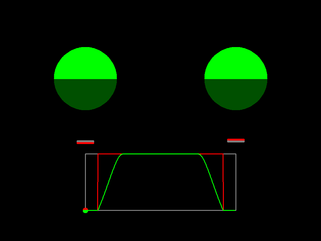
Observe the thinsat in the full power, maximum Night Light Pollution case. The white side facing the sun gathers full power when available, going to zero power as it passes into eclipse. But in the 90° to 150° position, and again in the 210° to 270° position, a non-zero-albedo front surface will reflect some light into the night sky. A large telescope tracking the thinsat will probably be able to detect it.
What if there are a trillion thinsats? The little dab of light becomes huge. They will add a glow to the night sky, approaching the brightness of the full moon. Nature depends on a dark night sky, and many species use the light from the full moon to navigate or synchronize reproduction. Too much light, and server sky becomes a new environmental hazard, rather than a solution to old ones.
The second animation, zero night light pollution, shows the thinsat turning towards the terminator (day-night boundary) as it enters the night sky. In this orientation, no light from the front of the thinsat can reach the night sky of the earth. The thinsat will keep turning when it passes into eclipse; with the right rotation rate going in, it will be oriented correctly when it comes out of eclipse.
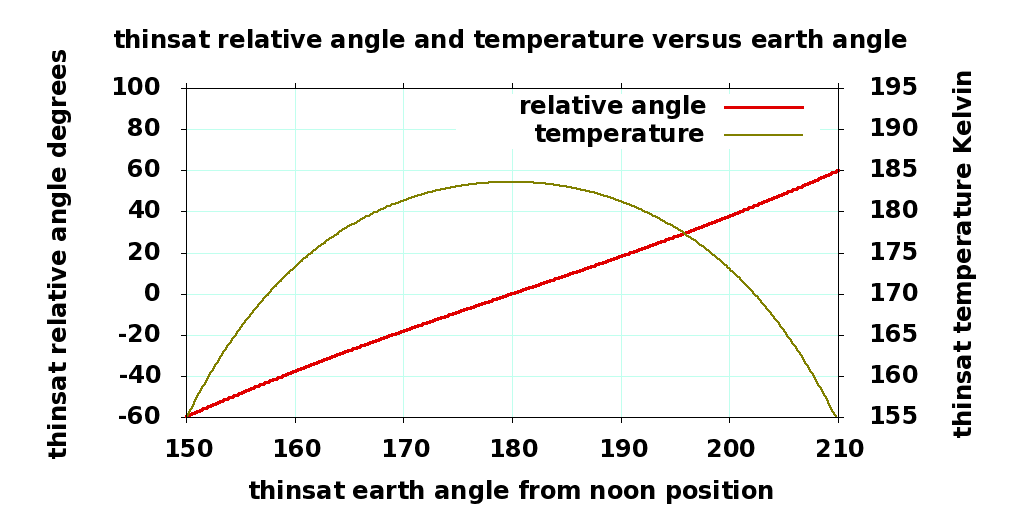
The red line on the big graph to the right shows the angle of the thinsat's "normal" (perpendicular vector from the front) relative to the center of the earth ("down"). It is not quite a straight line; the Earth's gravity field gets ever-so-slightly stronger towards the earth from the center of the thinsat's orbit, and weaker away from it That tiny tidal force is enough to accelerate the thinsat towards a 90° or 270° orientation, edge on to the center of the earth. We must add another 16.7% of rotational velocity going into eclipse to compensate.
Perhaps we will never launch a trillion thinsats. Perhaps we will never use up all 4 billion IPV4 internet addresses (Oops. We did!). Best to plan ahead, and design the correct architecture into the system from the beginning, and be prepared for success. As you will see, with the right architecture, the flip protects thinsats from thermal shock.
Absorbing heat from the earth during the night side flip
First, let's compute the infrared we get from the 260K earth. That will be a disk with a solid angle radius \rho_E of about 30 degrees. The distance or curvature of the disk does not matter, only the solid angle does. The amount of heat deposited on the Lambertian surface of the thinsat is a function of angle, the cross product of two vectors. One unit vector \vec P is perpendicular to the surface of the thinsat, the other unit vector \vec E is pependicular to the center of the disk.
The disk can be projected onto a unit sphere, and decomposed into rings with angular radius \phi and width d\phi , then further decomposed into pixel elements at angle \theta and width d\theta , an element with vector \vec \alpha( \theta, \phi ) . That vector can be decomposed into \vec \alpha( \theta, \phi )\parallel , a vector parallel to \vec D , and \vec \alpha( \theta, \phi )_\perp , perpendicular to \vec D . | \vec \alpha( \theta, \phi )_\parallel | = \cos( \phi ) and | \vec \alpha( \theta, \phi )_\perp | = \sin( \phi ) . If we sum the vectors \vec \alpha( \theta, \phi ) and \vec \alpha( (\theta + \pi), \phi ) , then the sin() perpendicular elements cancel, and so | \vec \alpha( \theta, \phi ) + \vec \alpha( (\theta + \pi), \phi ) | = 2 \cos(\phi) . The same is true for all pairs of elements around the circle, so the effective solid angle of the ring (radius 2 \pi \sin( \phi ) ) is 2 \pi \sin( \phi ) \cos( \phi ) d\phi = \pi \sin( 2 \phi ) d\phi .
We can easily integrate all those rings in the disk into a solid angle vector { \pi \over 2 } ( 1 - \cos( 2 \rho ) ) in direction of \vec D . The amount of heat radiation reaching the thinsat is proportional to { \pi \over 2 } ( 1 - \cos( 2 \rho ) ) ( \vec P \cdot \vec D ) . If the angle between \vec P and \vec D is e , then \vec P \cdot \vec D = \cos( e ) .
We know that if the thermally one-sided thinsat was pointed into a half-sphere, \rho = \pi / 2 and \vec P = \vec D , then the temperature of the thinsat equals the temperature of the half-sphere, T_s = T_h . The heat radiation would be proportional to \pi { T_h }^4 . If instead we are looking at the \rho_e radius earth ( temperature T_e ), at an angle of e from thinsat perpendicular, the amount of heat will be proportional to 0.5 ( 1 - \cos( 2 \rho_E ) ) \cos( e ) \approx 0.25 \cos( e ) and the temperature will be the 4th root of that quantity times T_e = 260K:
T_{thinsat} = \left( 0.5 ( 1 - \cos( 2 \rho_E ) ) \cos( e ) \right) ^ {1/4} T_{earth}
\rho_E = angular radius of earth ( approximately 30° for m288)
e = angle of earth from thinsat perpendicular ( -60° to 60° for m288)
At the equinoxes, the eclipse time is 1/6 of the 240 minute sidereal orbit, 40 minutes. At the start of eclipse, the thinsat points at the terminator, 30° away from the center or the earth, e = 60°, the heat is 1/8th of the full surround case, and the temperature drops towards 0.595 times 260K, or 155K. At the middle of the eclipse 20 minutes later, the backside points directly at the center of the earth, e = 0° and the temperature increases towards 184K. Over the next 20 minutes, the temperature drops back down towards 155K. The rate at which temperature changes will be inversely related to the small heat storage in the aluminum substrate; not very much for a thinsat!
An IRfiltered thinsat in max power mode (which doesn't flip) will capture only the slight amount of heat energy from the earth with wavelengths shorter than 3.5μm wavelength, then radiate it out the backside into 2.7K space. Depending on the sharpness of the filter, the thinsat might drop below 20K. Subjecting the thinsat to that kind of thermal shock for a few percent extra power is not worth it.
Version 4 thinsats with twice the radiator surface would drop temperature by another 16%, to 130K and 155K respectively with the backside flip. A version 4 thinsat in max power mode will range from 149K to 155K. So in every circumstance, the version 5 IR filtered thinsats stay warmer than version 4 thinsats.
Metal Grid Hot Mirror
A conductive aluminum grid, cell size around 2μm. It should be conductive enough to appear as a mirror at 3μm or longer wavelengths, as well as a front side conductor for the InP solar cells. Resist may be printable with contact inking of some sort; we do not need high yield for the links or the holes, a few missing links or filled holes will not change behavior much. |
Problems?
This is based on many assumptions:
A filter that reflects wavelengths longer than 3.5μm over wide angles is possible. I've been told this but need to verify it.
- The filter is less than 10 microns thick.
- The filter doesn't use very expensive materials.
- The filter tolerates high radiation doses.
It may be a "hot mirror" something like a stack of dielectric layers or a metal grid.
- The flip manuever requires significant angular velocity going into eclipse, hard to do when the thinsat is perpendicular to the sun. In reality, the thinsat will have some exposed angle at start of eclipse, and some light-pollution minimizing strategy to get there. We are in the "triple lambert" zone, the power captured from the sun is proportional to the cosine of perpendicular to the sun, and the light scattered into the night sky is also. The sky into which it scatters is nearly perpendicular, with big lambert attenuation, too.
