One Dimensional Grating Lobes
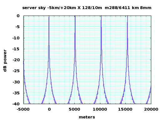
Traditional phased arrays have a problem called grating lobes. If the spacing of the transmitter nodes is wider than the wavelength of the sine wave source, then there are many ground spots and many angles that show a constructive interference maximum. These spatial lobes are called grating lobes, and resemble the off-axis lobes in an x-ray crystallography pattern. If the precise spacing of thinsats is 10 meters, there will be grating lobes at 0.046 degree spacings, or a ground spacing of 5.1 kilometers. Although the main ground spot of a large array of transmitters will be narrow, there will be many more than one.
|
The grating lobes near the main ground spot for a 10 meter spacing and an 8mm wavelength, 128 elements in a line. The peaks shown are actually the maximum of many peaks - the lobes have a fine structure. |
There is a solution. Unlike a traditional phased array, the transmitters can be placed in an unevenly spaced (or even random) array, and the array spacing can be adjusted and optimized in real time. This destroys the exact periodicity of the array, and flattens the lobes into the noise floor. While the same amount of unwelcome power is splattered across the landscape, at least it is not focused into a few spots (the sidelobe power would only be reduced if the transmitting antennas were close enough to couple). If the randomly spaced elements are still phased for a maximum at the primary lobe, the power of that lobe is unaffected.
This is easiest to show (and compute) for a linear array, although the same procedure may be extended to a three dimensional array. Many different spacing algorithms is possible. Random dithering around a precision center seems to average out to produce grating lobes (just as thermal vibration smears but does not eliminate lobes in x-ray crystalography). However, a random walk distance algorithm, where a random amount is added to each spacing between transmitters, does a good job of smearing out grating lobes. The following graphs show the results of adding uniform random spacings of 0m, 1m, 2m, and 3m to the basic 10m spacing. The distance scale is varied from -1km/1km to -1000km/5000km.
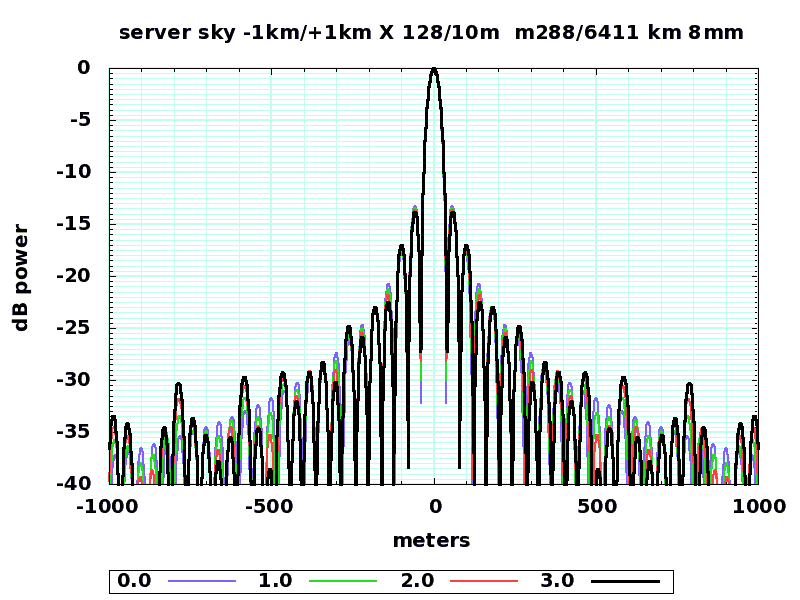
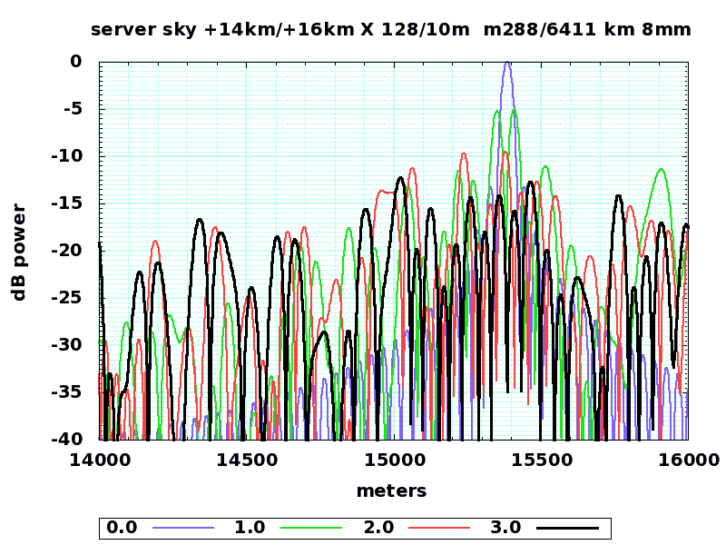
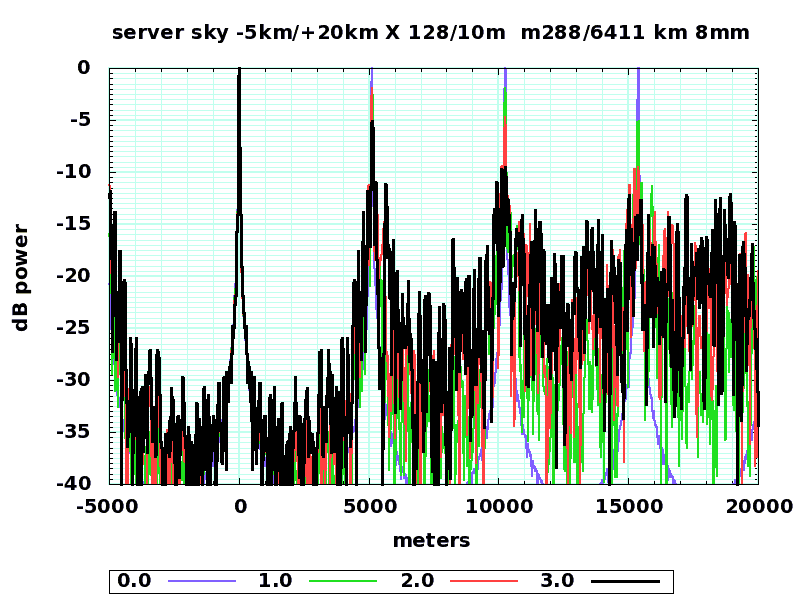
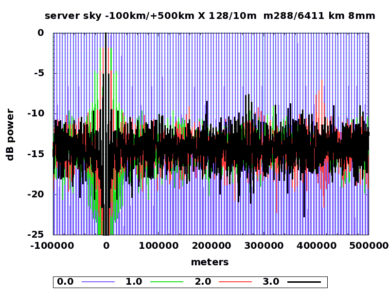
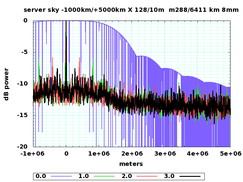
This is just a first pass test using this C program and gnuplot using a command file like this. A two dimensional extension and a three dimensional extension is needed (which will be very compute intensive), and it is likely that the proper nonrandom spacing algorithm (perhaps based on a windowed fourier transform) will produce a better spacing algorithm.
Volunteer Opportunity
Programming and math savvy individuals can search for better/simpler spacing methods, as well as computational methods for quickly estimating maximum and average sidelobe energy. Animation savvy individuals could transform these methods into movies showing the tracking of ground spots from a moving array.

