The Space Environment
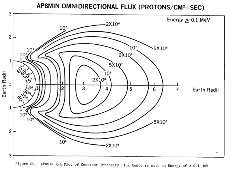
The inner and outer van Allen belts
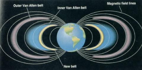
The M288 orbit (4 hour sidereal, 5 orbits per day relative to the earth) is located at a radius of 12789 km, about 6400 kilometers altitude. That places it between the inner and outer van Allen belts. This is a relatively high radiation environment compared to low earth orbit, but lower than the center of the belts. Recent advances in semiconductor technology permit unshielded electronics to operate in this region, and Server Sky takes advantage of that work. Traditional satellites are damaged by this much radiation; consequently, there are few satellites operating in these orbits.
Ionizing radiation and semiconductor damage
Ionizing radiation does five nasty things to semiconductors:
- Latchup
- SEU - single event upsets, bit flipping
- Oxide charging
- Flash memory errors
- Crystal lattice degradation
Server sky is designed to resist these effects. The space radiation environment is well characterized and computer models exist, such as AF-GEOSPACE. The radiation effects can also be empirically tested in ground laboratories, at high dose rates, and extrapolated to the effects of years of space radiation exposure.
Latchup
|
|
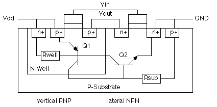
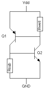
The NMOS and PMOS transistors in a CMOS integrated circuit are often isolated from each other by diode junctions. The first drawing above shows a PFET in an N well next to an NFET in a P well. A P source, N well, P well, and N source make a PNPN junction stack, as shown in the second drawing. This is much like a device called a Silicon Controlled Rectifier or SCR, which is a commonly used latching electrical switch. When the currents are high enough in an SCR, a positive feedback loop is established, latching the device in a conductive state. In this case, that can form a high current conducting path between the power supply and ground. This heats up the silicon, and can destroy it.
An ionizing radiation particle can create a temporary high current path that can activate an SCR and cause latchup. This is a problem in electronics exposed to radiation. It is usually mitigated by special design for latchup resistance, and heavy shielding for the electronics. Server Sky cannot afford the shielding weight, or the special design.
The SCR path cannot be activated if the voltage between the supply and ground is less than a diode turn-on voltage (typically more than 0.7V). The electronics in a thinsat are powered by a single-junction solar cell, which is a large forward-biased silicon diode. It cannot produce more than about 0.6V. A thinsat cannot latch up
In some special circumstances, circuits called "voltage multipliers" may be used to construct higher voltages for special needs. However, the voltage multipliers will be low current and easily switched off, so damaging high current latchup will not be possible in these circuits, either.
Single Event Upsets
The charge deposited by an ionizing particle can temporarily overwhelm a logic gate, or change the state of a register bit. This can cause incorrect computations. Often the cost of such an error is small, for example when computing the I and Q signal of a software defined radio - a calculation error will just create a little extra noise. The cost is unacceptable when determining CPU state, performing calculations, and such. While computation errors can be detected and corrected with redundancy, either by duplicating hardware or by repeating calculations, redundancy lowers performance and computational efficiency.
One promising approach is to use the RAZOR error correction technology being developed by the University of Michigan, MIT, and Intel. Digital integrated circuits are typically designed for high "noise margin", with extra power and voltage swing added, and clock rates reduced, to reduce the chances of a logic failure to infinitesimal probabilities. However, this is costly and reduces performance. RAZOR greatly reduces the noise margin, greatly improving the performance, but at the cost of frequent errors. RAZOR adds circuitry to detect these errors, and repeat the calculations when they occur. The system can be tuned so that the performance improvement greatly exceeds the cost of the extra calculations, almost doubling overall performance. RAZOR technology will be common in logic chips and processors in a few years.
Radiation-initiated single event upsets are just another kind of error, which can be detected and corrected by RAZOR-like technology. Since these SEU events may occur in the error correction logic itself, there will need to be additional redundant logic in the correction circuitry, but that will still be a net win over adding redundancy to the entire chip.
Oxide Charging
Silicon dioxide develops a positive charge when irradiated. An ionizing particle passes through, and generates hole-electron pairs. The electrons are highly mobile, and diffuse or drift out, while the holes get trapped, and leave a positive charge. Hafnium oxide develops a negative charge, trapping electrons. Recent work by Dixit shows that a stack of both shows promise as a rad-hard gate oxide, withstanding 10Mrad from a Cobalt 60 source with minimal shifts.
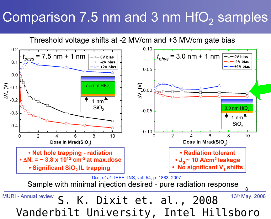
The study above used 10KeV 'soft' X-rays for irradiation; perhaps a wider spectrum of radiation energies, as would be found in the Van Allen belt, would preferentially charge either the !HfO or the SiO2, leaving a residual imbalance? In any case, it does demonstrate how modern gate oxides may be much more rad hard than older technologies.
Flash Memory Errors
Error correcting memory - MoreLater
Crystal Lattice Damage
Annealing - MoreLater
Space Junk and Debris
Collisions are a problem, especially for arrays like server sky which will put huge numbers of assets into carefully defined and controlled orbits.
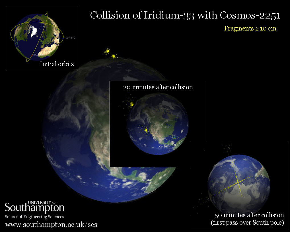
The above picture illustrates the 2009 February collision between Iridium-33 and the abandoned Cosmos-2251 . The collision destroyed a $250M asset, and created hundreds of large pieces of debris. Server Sky cannot be permitted to come close to such expensive assets as the Iridium communication satellites. The consequences of a collision are too costly.
On the other hand, thinsats are cheap, and destroying one in a collision is unfortunate but not especially expensive. The main cost of a thinsat collision with space junk is more space junk, which can damage other thinsats. More robust objects (like traditional big-iron satellites) encountering thinsat fragments will probably lose a solar cell or two on the skin, but won't be destroyed. Still, it is bad manners to add to the debris problem.
Fortunately, thinsats can be manuevered out of the way of predicted collisions, if the predictions are accurate enough. Since they maneuver by light pressure, they have an unlimited supply of very low thrust - given time, they can change orbit sufficiently to stay more than a kilometer away from any tracked impactor.
Server sky will be deployed in orbits higher than most space junk. The version 0.1 design deploys thinsats in m288 orbits, with semimajor axes of 12781 kilometers and average altitudes of 6411 kilometers. The vast majority of space debris is in lower orbits - it requires high launch velocities to even reach those altitudes.
Click on the drawing for a higher resolution drawing.
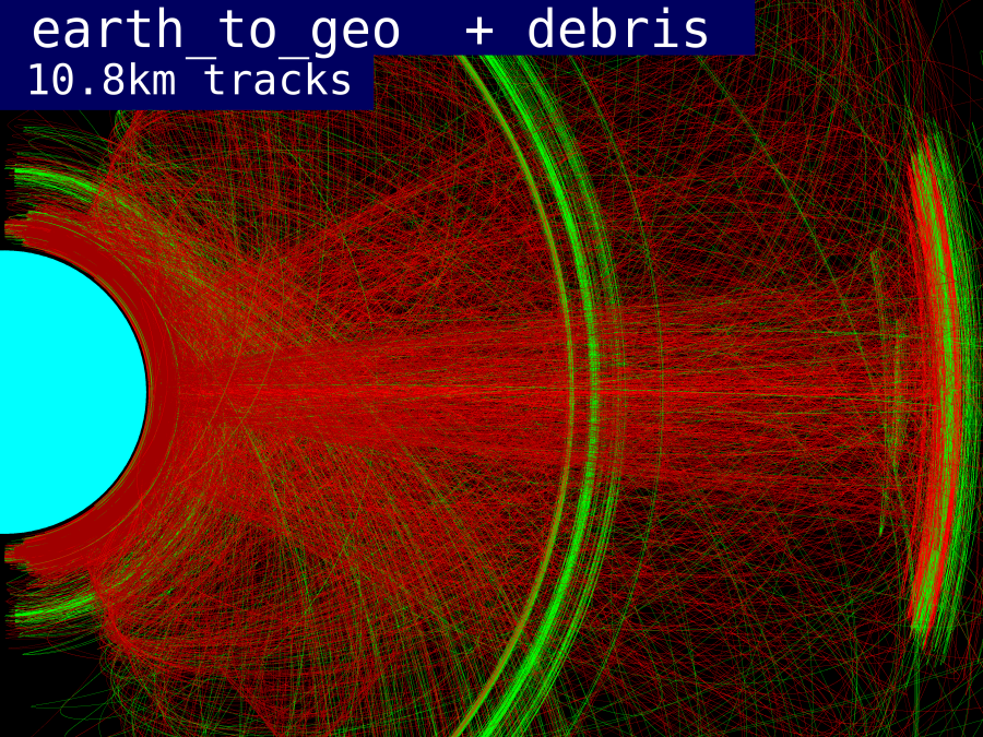
The above plot shows all the objects tracked by NORAD in orbits up to geosyncronous altitude. This is an "HV" plot, with the horizontal H component representing the radius in the equatorial plane, and the vertical V component representing the distance above the plane. All orbits will look like an ellipse or banana shape plotted in this way. Red is debris, darker red is spent rocket bodies, and green is useful satellite assets. At any given time, the objects are in one place in their orbit.
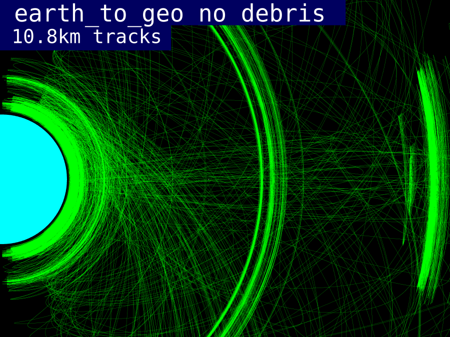
The thick cloud near the earth is LEO or Low Earth Orbit. These are the easiest orbits to reach, and the vast majority of useful satellite assets, and most of the space junk, is located here. The stripes on the right of the drawing are satellites in Geosynchronous orbits. These orbits are well managed, with satellites actively positioning themselves in the right places, and spent satellites and rocket bodies in higher and lower orbits.
In between GEO and low earth orbit is "MEO", or Medium Earth Orbit. The first interesting band of MEO is the green band extending above and below the poles, a bit further out than LEO. This region contains the Iridium and Globestar communication satellite clusters - hundreds of satellites that form a communication mesh for telephone and other low latency communication. Sadly for the operators of these systems, fiber optic communication got a whole lot better, and in most parts of the world that is a cheaper way to move telephone and data globally. The operators of Iridium and Globestar went bankrupt.
The bright green bands running through the center of the drawing are the GPS/Navstar and GLOSNAS navigation and positioning satellites.
The distances represented by this plot is vast - 44000 kilometers wide, 33000 kilometers high, more than 10 times the land surface of the earth. The volume of space represented is enormous, 2E14 cubic kilometers, or 200 trillion cubic kilometers, or 400 thousand times the volume of atmosphere in which we fly all the airplanes in the world. The tracked items are small from centimeter scale (debris) to 100 meter scale (international space station). So an "accurate" drawing would be completely blank.
There are far more airplanes airborne at any given time than satellites, and most satellites are much smaller than most airplanes. So why are their any collisions at all. There are occasional rare collisions because the orbiting bodies move continuously at high speed, the orbits differ in period and relative inclination, and after satellites fail or expend all their thruster fuel, cannot avoid predicted collisions. Airplanes are confined to flight levels so they should never intersect with high closing velocities. They are actively tracked with radar and change course to avoid other airplanes. Satellites follow no such discipline.
NORAD tracking information is made with ground-based radars in a very few spots around the earth - most of Low Earth orbit is unobserved. Atmospheric drag on the lowest objects can significantly alter the orbits. With current capabilities, it is very difficult to predict future satellite orbits better than a kilometer or so. Since thruster fuel is limited, avoiding every low-probability collision event is a futile exercise. When we develop the ability to track objects to much higher precision, we will be able to accurately predict future collisions, and make small thruster changes to avoid them.
Above is the same plot without the debris and spent rocket bodies - these are mostly satellites in use.
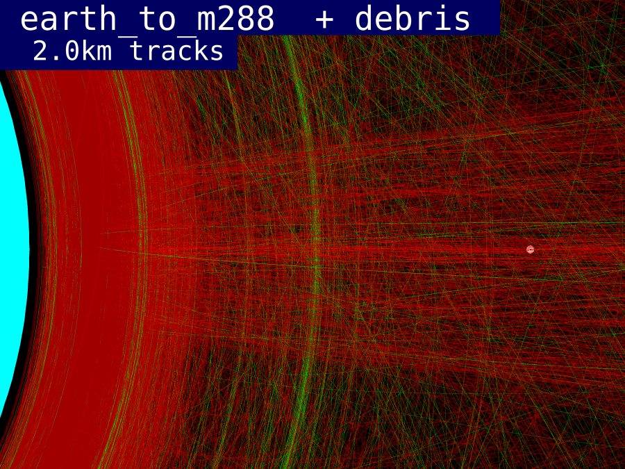
Server sky version 0.1 will be located in m288, about one earth radius in altitude. The 100 kilometer dot to the right of the drawing represents the orbits used by server sky. There is still some debris and a few useful assets at that altitude, but it is not nearly as crowded as low earth orbit.
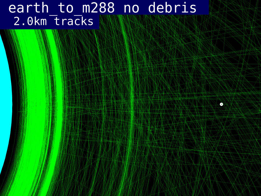
Above is the same plot without the debris. Only a few assets ever get close to the m288 orbit.
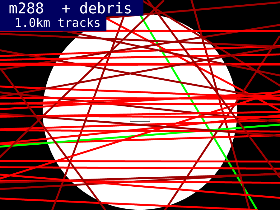
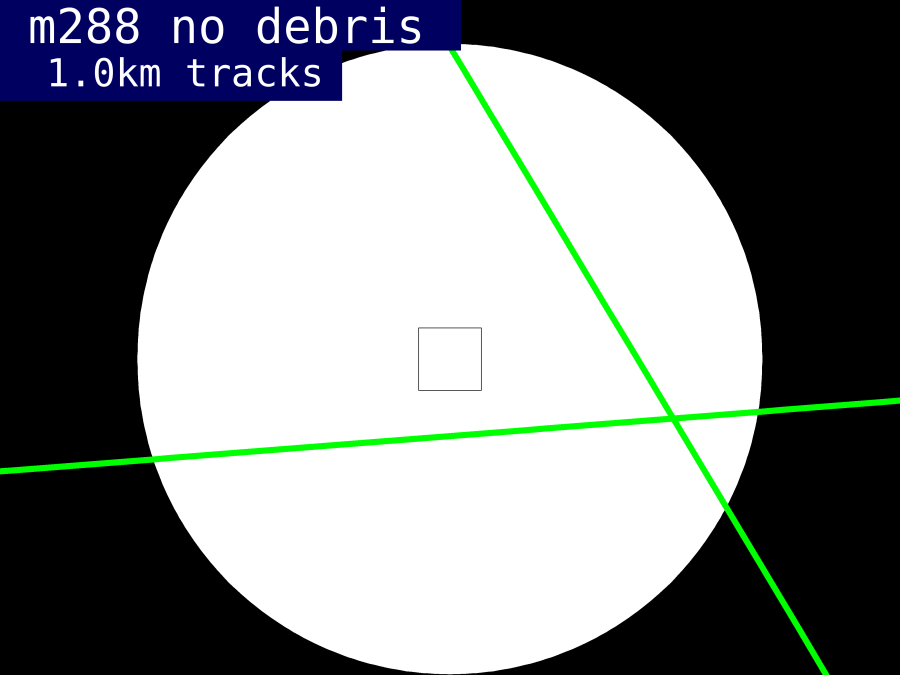
Above is a plot of just the m288 region. The square in the center of the plot is 10 kilometers on a side, about as big as San Francisco. If the Server Sky orbits are threaded through the white spaces, they will never encounter one of the Norad tracked space objects.
Above is the same plot without the debris. Only two assets cross the server sky orbit at this time; MOLNIYA 3-3 and BSAT 2B. The Molniya was launched in 1975 and may no longer be in use. The BSAT is a Japanese communication satellite that failed to reach geosynchronous orbit. So even these are not valuable assets. If the debris and failed satellites are removed, the orbits should be completely clear and usable for Server Sky. Until then, accurate tracking and avoidance should free up most of the orbit.
Surface charging
Most of the area of a thinsat will be solar cells, with low voltages across the surface. If the electrochromic thrusters have indium tin oxide conductors on both sides, the outer conductors may be grounded relative to the rest of the thinsat. As all surfaces will be conductive, and at voltages less than one or two volts, there is no opportunity for arcing across surfaces, which sometimes happens to geosynchronous satellites in the solar wind ( see SMAD page 212-214 ).
Night Side Temperature
When the thinsat orbit takes it to the night side of the earth, for about 1/6th of its orbit, it will only be heated by the thermal radiation from the earth, filling 0.5*(1 - cos(30deg)) or 6.7% of the sky with a black body temperature of 250K. At equilibrium, the temperature of the thinsat will be 250K times the fourth root of 0.067, or around 127K ( -146C ).
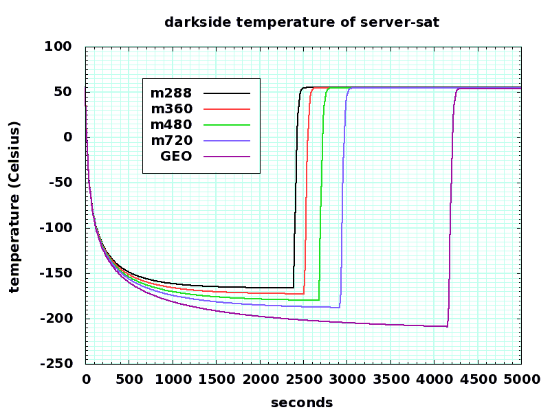
Above is a plot of how the temperature varies as a thinsat passes behind the earth. The dark time corresponds to the spring and autumn equinoxes; in winter and summer, the shadow time will be a little smaller for m288 orbits. In GEO and higher orbits, there will be no shadow at all in winter and summer, though there will still be shadows in spring and fall.
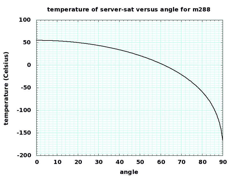
Turning the thinsat means it intercepts less solar energy. This will cause it to cool down.
Drag
References
http://www.isde.vanderbilt.edu/content/muri_2008/dixit_muri2008.pdf Sriram Dixit et. al. at Vanderbilt University. Recent work on HfO/SiO2 stacked gates and radiation resistance.
http://apollo.cnuce.cnr.it/rossi/publications/iau/node2.html A 1994 estimate of space debris. There is more now, but it follows the same pattern.
