|
Size: 1519
Comment:
|
Size: 4405
Comment:
|
| Deletions are marked like this. | Additions are marked like this. |
| Line 1: | Line 1: |
| = Radar = -------- == SSPS Interference with Airport Radar == |
## page was renamed from SPSRadar ## page was renamed from Radar = SSPS Interference with Airport Radar = |
| Line 5: | Line 5: |
| === ARSR-4 and ASR-11 Radars === [[attachment:AAPG_ICD_v44-2.pdf | NWS Supplemental Product Generator (SPG)for the ARSR-4 and ASR-11 Radars Product Specification & Interface Control Document]] |
|
| Line 12: | Line 8: |
| Line 15: | Line 10: |
| PSR Probability of Detection: The PSR shall be capable of detecting a 1.0 m2 Radar Cross Section (RCS), Swerling 1 target to a range of 55 nmi in the clear and at the nose of the beam with a single scan Pd of 0.8 and a Probability ofFalse Alann (PFA) of 10-6 • | PSR Probability of Detection: The PSR shall be capable of detecting a 1.0 m^2^ Radar Cross Section (RCS), Swerling 1 target to a range of 55 nmi in the clear and at the nose of the beam with a single scan Pd of 0.8 and a Probability of False Alann (PFA) of 10-6 • |
| Line 19: | Line 14: |
| || || ARSR-4 || ASR-11 || || Band || L Band || S Band || || Peak Power || 60 kW || 25 kW || || Average Power || || 2.1 kW || || Wavelength cm || 21.4-24.7 || 10.3-11.1 || || Frequency GHz || 1.21-1.39 || 2.7-2.9 || || Max interference || ? || -117 || dBm/MHz!! assumed EIRP || || LNA bandwidth || ? || ? || || IF bandwidth || ? || 1 MHz || Table D2 pg 107 13-490 || || Polarization || Linear || Linear || || || Circular || Circular || || Beam width || 1.41° || 1.41° || || Beam Elevation || 2.2° || 4.8° || || Antenna Gain || || 34dB || || Antenna Size || 9 x 7 m || 5 x 3 m || || Pulse width || || 1μs || || || || 80μs || || Coverage nm || 250 nm || 60 nm || || Coverage km || 463 km || 111 km || || Scan period || 12 sec || 12 sec || || Weather map || 36 sec || || || # deployed || 43 || 213 || |
|
| Line 20: | Line 37: |
| || || ARSR-4 || ASR-11 || || Band || L Band || S Band || || Peak Power || || 25 kW || || Average Power || || 2.1 kW || || Wavelength cm || 21.4-24.7 || 10.3-11.1 || || Frequency GHz || 1.21-1.39 || 2.7-2.9 || || Polarization || Linear || Linear || || || Circular || Circular || || Beam width || 1.41° || 1.41° || || Beam Elevation || 2.2° || 4.8° || || Coverage nm || 250 nm || 60 nm || || Coverage km || 463 km || 111 km || || Scan period || 12 sec || 12 sec || || Weather map || 36 sec || || || # deployed || 43 || 213 || |
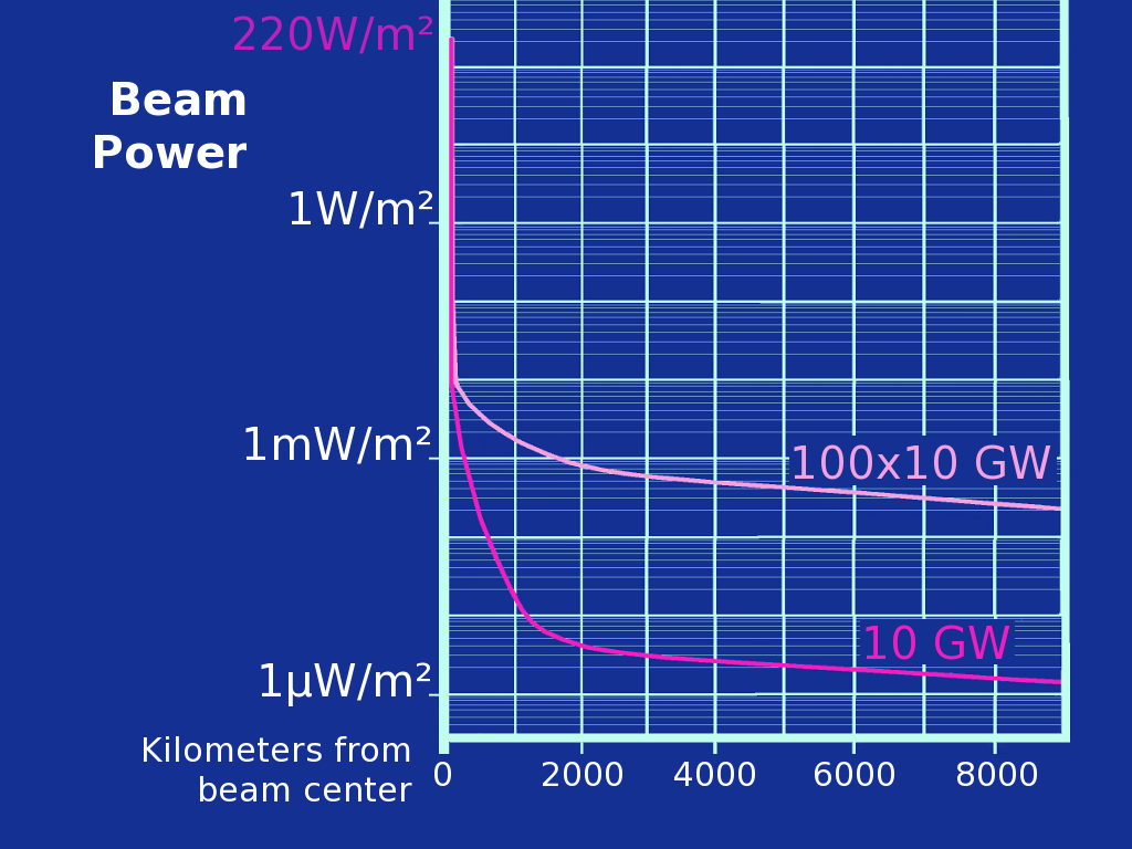
[[attachment:AAPG_ICD_v44-2.pdf | NWS Supplemental Product Generator (SPG)for the ARSR-4 and ASR-11 Radars Product Specification & Interface Control Document]] [[http://www.ntia.doc.gov/files/ntia/publications/13-490_1_.pdf | 13-490 ]] Effects of Wimax on airport radar and weather radar. ----- === Guessing about radar === If we presume the beam energy is confined to an area of 6.77 square degrees out of a 41253 square degree sky, that would be a gain of 37.85 dB. Since the specified gain is 34 dB, more power ends up in sidelobes than presumed. If the antenna gain is 34 dB, and the peak pulse power is 25 kW, that suggests that the EIRP is 63 MW. A 1 m^2^ target at a range of 111 km gets 400 microwatts of illumination. If that radiates back with a 1 steradian spread, it delivers 83 pW to the antenna, -70 dBm ? ----- ||{{attachment:ArndtSlideV4.png||height=300}}|| '''Sidelobe graph, Cleaned up from Arndt 1978'''<<BR>><<BR>> Note - This is the '''theoretical, average''' power without atmospheric scattering (rain, dust, etc.). Assume 1mW/m², depositing 15 mW of carrier on a 5x3 meter antenna.|| ||{{attachment:SSPSmag.png||height=300}}||This is the noise from a [[ attachment:Kyoto2004MagnetronA.pdf | magnetron]]. Not sure how to interpret this - if we assume a 1 MHz bandwidth and extrapolate to -70 dBc/Hz at 2.7 GHz, how much noise power is that assuming a 15 mW carrier hitting the 5x3 meter antenna?|| Of course, the SSPS is not pointed at a radar, but it does create 100's of megawatts of sidelobe power lighting up the whole earth. The radar dish does not point at SSPS overhead, but if there are 100 in orbit, some will be near the horizon within the 360 degree antenna horizontal and 40 degree vertical scan. A radar will see any SSPS that appears near the horizon, and at low elevation there will be significant atmospheric and terrain scattering. == Pulsed SSPS as Bistatic Radar Illumination Source == ² '''If you can't fix it, feature it.''' What if we used the SSPS beam as the source of radar illumination power? √ SSPS efficiency is limited by the rectifying diode drop; a Schottky diode requires perhaps 0.4V to turn on, which is subtracted from the peak dipole voltage. For a given rectenna power density, say 100 W/m², the peak voltage field is √2PR, where R is the 377 Ω/□ impedance of free space, or 275 V/m. For a 2.45 GHz beam, a dipole antenna is 6.1 cm, so the peak dipole voltage is 16.8 volts, unloaded. My guess is that with a matched load, this is cut in half, to 8.4 volts. MoreLater |
SSPS Interference with Airport Radar
ARSR-4: Air Route Surveillance Phased array Radar
ASR-11: Airport Surveillance Radar, Terminal Area
( AN/GPN-30 )
PSR Probability of Detection: The PSR shall be capable of detecting a 1.0 m2 Radar Cross Section (RCS), Swerling 1 target to a range of 55 nmi in the clear and at the nose of the beam with a single scan Pd of 0.8 and a Probability of False Alann (PFA) of 10-6 •
Operational Subclutter Visibility: Operational SCV shall be 42 dB minimum at all ranges for nonfluctuating targets.
|
ARSR-4 |
ASR-11 |
|
Band |
L Band |
S Band |
|
Peak Power |
60 kW |
25 kW |
|
Average Power |
|
2.1 kW |
|
Wavelength cm |
21.4-24.7 |
10.3-11.1 |
|
Frequency GHz |
1.21-1.39 |
2.7-2.9 |
|
Max interference |
? |
-117 |
dBm/MHz!! assumed EIRP |
LNA bandwidth |
? |
? |
|
IF bandwidth |
? |
1 MHz |
Table D2 pg 107 13-490 |
Polarization |
Linear |
Linear |
|
|
Circular |
Circular |
|
Beam width |
1.41° |
1.41° |
|
Beam Elevation |
2.2° |
4.8° |
|
Antenna Gain |
|
34dB |
|
Antenna Size |
9 x 7 m |
5 x 3 m |
|
Pulse width |
|
1μs |
|
|
|
80μs |
|
Coverage nm |
250 nm |
60 nm |
|
Coverage km |
463 km |
111 km |
|
Scan period |
12 sec |
12 sec |
|
Weather map |
36 sec |
|
|
# deployed |
43 |
213 |
13-490 Effects of Wimax on airport radar and weather radar.
Guessing about radar
If we presume the beam energy is confined to an area of 6.77 square degrees out of a 41253 square degree sky, that would be a gain of 37.85 dB. Since the specified gain is 34 dB, more power ends up in sidelobes than presumed.
If the antenna gain is 34 dB, and the peak pulse power is 25 kW, that suggests that the EIRP is 63 MW. A 1 m2 target at a range of 111 km gets 400 microwatts of illumination. If that radiates back with a 1 steradian spread, it delivers 83 pW to the antenna, -70 dBm ?
|
Sidelobe graph, Cleaned up from Arndt 1978 |
|
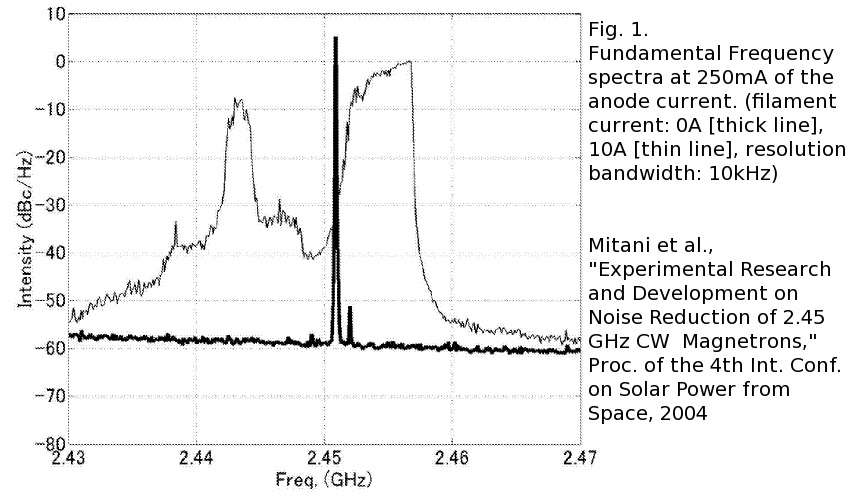
This is the noise from a magnetron. Not sure how to interpret this - if we assume a 1 MHz bandwidth and extrapolate to -70 dBc/Hz at 2.7 GHz, how much noise power is that assuming a 15 mW carrier hitting the 5x3 meter antenna? |
Of course, the SSPS is not pointed at a radar, but it does create 100's of megawatts of sidelobe power lighting up the whole earth. The radar dish does not point at SSPS overhead, but if there are 100 in orbit, some will be near the horizon within the 360 degree antenna horizontal and 40 degree vertical scan. A radar will see any SSPS that appears near the horizon, and at low elevation there will be significant atmospheric and terrain scattering.
Pulsed SSPS as Bistatic Radar Illumination Source
² If you can't fix it, feature it. What if we used the SSPS beam as the source of radar illumination power? √ SSPS efficiency is limited by the rectifying diode drop; a Schottky diode requires perhaps 0.4V to turn on, which is subtracted from the peak dipole voltage. For a given rectenna power density, say 100 W/m², the peak voltage field is √2PR, where R is the 377 Ω/□ impedance of free space, or 275 V/m. For a 2.45 GHz beam, a dipole antenna is 6.1 cm, so the peak dipole voltage is 16.8 volts, unloaded. My guess is that with a matched load, this is cut in half, to 8.4 volts. MoreLater


