|
Size: 765
Comment:
|
← Revision 24 as of 2021-06-19 05:07:19 ⇥
Size: 3488
Comment:
|
| Deletions are marked like this. | Additions are marked like this. |
| Line 4: | Line 4: |
| [[t01.c | t01.c source]] - - - - [[tor00.hc | tor00.hc subroutines and include file ]] <<BR>><<BR>> | |
| Line 5: | Line 6: |
| [[t04.c | t04.c source]] - - - - [[tor01.hc | tor00.hc subroutines and include file ]] <<BR>><<BR>> | |
| Line 6: | Line 8: |
| [[t08.c | t08.c source]] - - - - [[tor00.hc | tor00.hc subroutines and include file ]] <<BR>><<BR>> | |
| Line 7: | Line 10: |
| [[t12.c | t12.c source]] - - - - [[tor00.hc | tor00.hc subroutines and include file ]] <<BR>><<BR>> | |
| Line 8: | Line 12: |
| [[t16.c | t16.c source]] - - - - [[tor00.hc | tor00.hc subroutines and include file ]] <<BR>><<BR>> | |
| Line 9: | Line 14: |
| [[t24.c | t24.c source]] - - - - [[tor00.hc | tor00.hc subroutines and include file ]] <<BR>><<BR>> | |
| Line 10: | Line 16: |
| [[t25.c | t25.c source]] - - - - [[tor00.hc | tor00.hc subroutines and include file ]] <<BR>><<BR>> | |
| Line 11: | Line 18: |
| [[t26.c | t26.c source]] - - - - [[tor00.hc | tor00.hc subroutines and include file ]] <<BR>><<BR>> | |
| Line 12: | Line 20: |
| [[t27.c | t27.c source]] - - - - [[tor00.hc | tor00.hc subroutines and include file ]] <<BR>><<BR>> | |
| Line 13: | Line 22: |
| [[t28.c | t28.c source]] - - - - [[tor00.hc | tor00.hc subroutines and include file ]] <<BR>><<BR>> | |
| Line 14: | Line 24: |
| [[t41.c | t41.c source]] - - - - [[tor00.hc | tor00.hc subroutines and include file ]] <<BR>><<BR>> | |
| Line 15: | Line 26: |
| [[t42.c | t42.c source]] - - - - [[tor00.hc | tor00.hc subroutines and include file ]] <<BR>><<BR>> <<Anchor(ApogeeSkew)>> |
|
| Line 18: | Line 33: |
| Here is an array of 125 server-sats in a 3 dimensional equal-spacing grid, looking inwards towards the ground as the array completes a 4 hour orbit. In actual fact, maneuvering will be used so that all the server-sats are not obscuring each other from the ground, or shading each other from the sun. As well, they will be offset to avoid grating lobes in the RF pattern. But this sure is pretty... | Here is an array of 125 thinsats in a 3 dimensional equal-spacing grid, looking inwards towards the ground as the array completes a 4 hour orbit. The rows of five thinsats follow each other in their orbits, separated very slightly in time. You can see the rows apparently rotating away and backwards, or towards and forwards, completing a rotation around the central orbit (gray) once per orbit. Watch the white circles make one loop, from back to top to front to bottom and back again. |
| Line 20: | Line 35: |
| {{ attachment:ap01.swf }} | As a row of thinsats moves from the back towards the top, it moves forwards in the orbit by twice its spacing from the center orbit. This is '''apogee skew''', where the satellites at the midpoints between perigee and apogee are skewed towards apogee. This skew is caused by the higher speed and shorter path on the perigee side of the orbit. Thinsat sizes are exaggerated compared to their spacing, and the whole array shown orbiting the earth is hugely exaggerated. The thinsats are actually smaller compared to their spacing, and slightly offset so they do not obscure each others radio path to the ground, or shade each other from the sun. They also have offsets to reduce grating lobes in the RF pattern. But the even spacing is prettier... {{ attachment:ap02.png | | width=1000 }} [[attachment:ap02.c | ap02.c source ]] ... (needs libgd and apngasm) ---- The three dimensional grid illustrated above shows the orbital dynamics, but a server sky thinsat array will probably map onto the surface of a squashed ellipsoid, look for later work on this website. Interarray spacings may look like this grid, although at extreme densities (terawatts of energy collection) the night-time sky pollution effects will be unacceptable. The effects will be 30 times smaller at GEO, due to inverse square attenuation, but this does place an ecological-effects upper limit on the deployment of SSPS. |
Toroidal Orbits
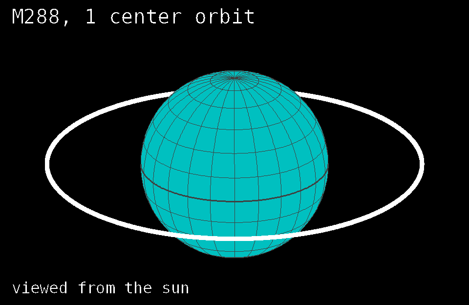 t01.c source - - - - tor00.hc subroutines and include file
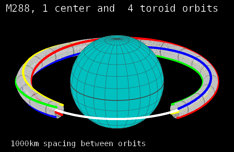 t04.c source - - - - tor00.hc subroutines and include file
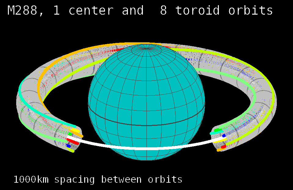 t08.c source - - - - tor00.hc subroutines and include file
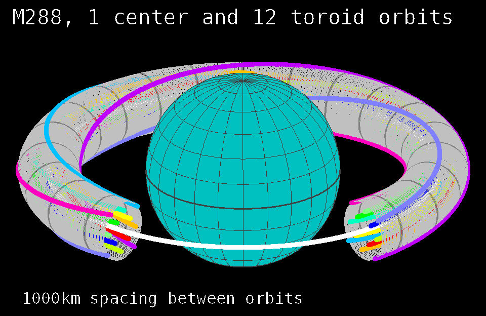 t12.c source - - - - tor00.hc subroutines and include file
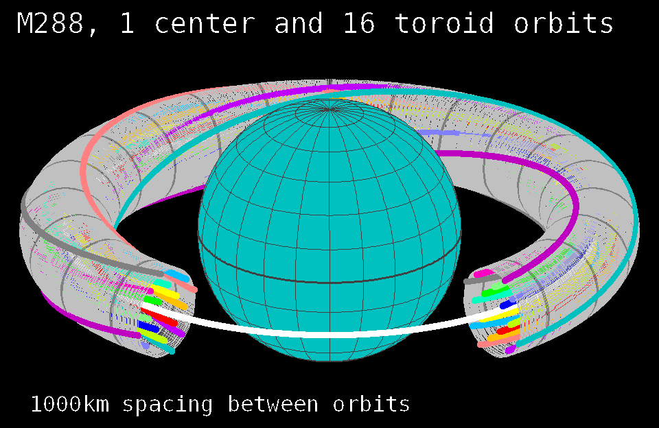 t16.c source - - - - tor00.hc subroutines and include file
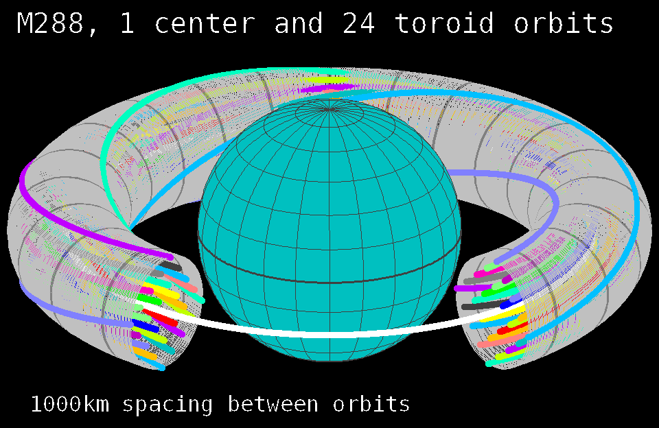 t24.c source - - - - tor00.hc subroutines and include file
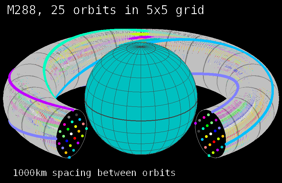 t25.c source - - - - tor00.hc subroutines and include file
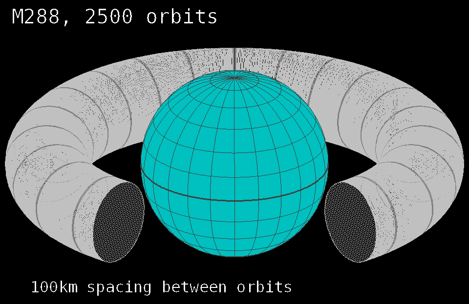 t26.c source - - - - tor00.hc subroutines and include file
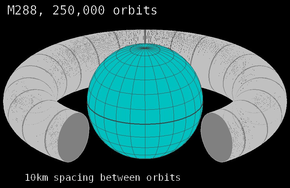 t27.c source - - - - tor00.hc subroutines and include file
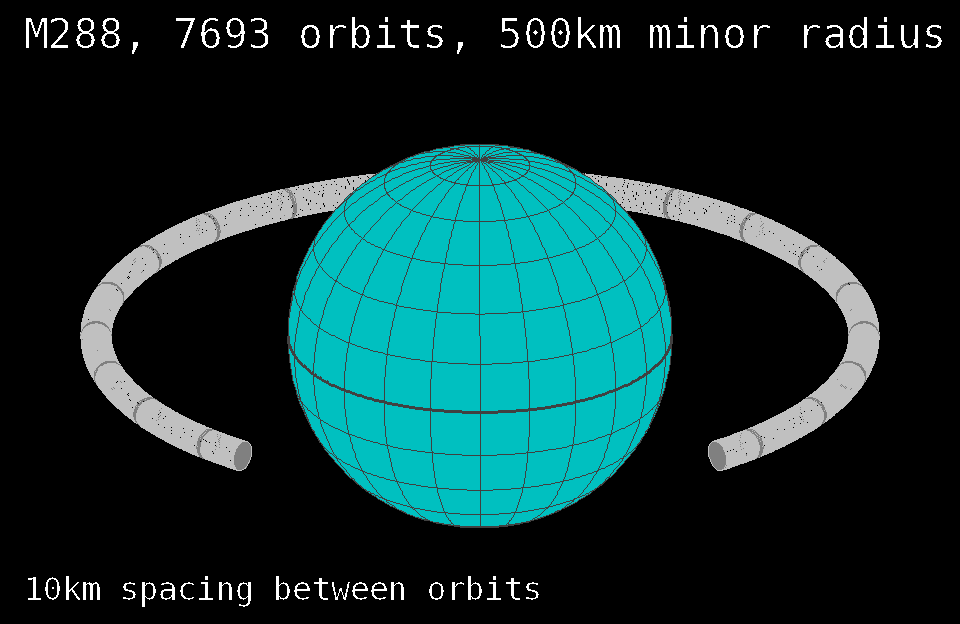 t28.c source - - - - tor00.hc subroutines and include file
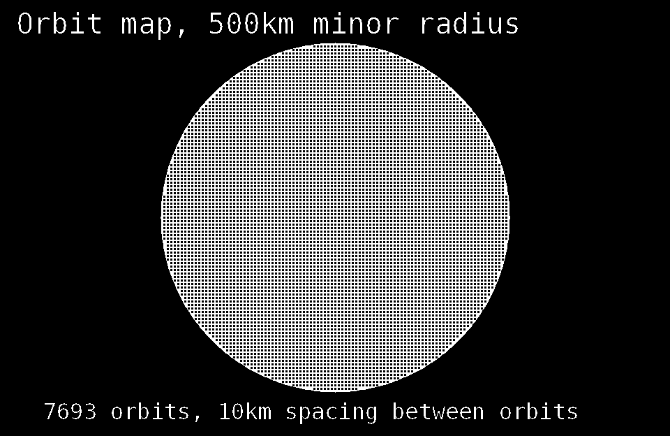 t41.c source - - - - tor00.hc subroutines and include file
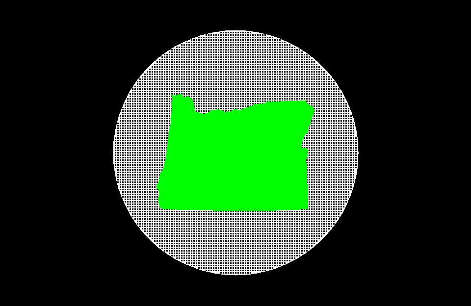 t42.c source - - - - tor00.hc subroutines and include file
Apogee Skew
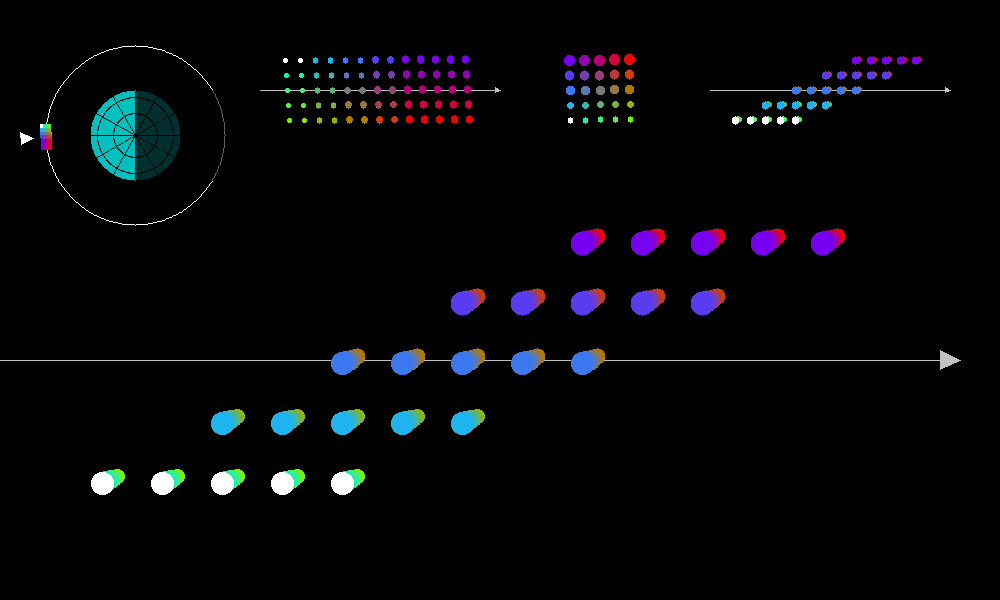
Here is an array of 125 thinsats in a 3 dimensional equal-spacing grid, looking inwards towards the ground as the array completes a 4 hour orbit. The rows of five thinsats follow each other in their orbits, separated very slightly in time. You can see the rows apparently rotating away and backwards, or towards and forwards, completing a rotation around the central orbit (gray) once per orbit. Watch the white circles make one loop, from back to top to front to bottom and back again.
As a row of thinsats moves from the back towards the top, it moves forwards in the orbit by twice its spacing from the center orbit. This is apogee skew, where the satellites at the midpoints between perigee and apogee are skewed towards apogee. This skew is caused by the higher speed and shorter path on the perigee side of the orbit.
Thinsat sizes are exaggerated compared to their spacing, and the whole array shown orbiting the earth is hugely exaggerated. The thinsats are actually smaller compared to their spacing, and slightly offset so they do not obscure each others radio path to the ground, or shade each other from the sun. They also have offsets to reduce grating lobes in the RF pattern. But the even spacing is prettier...
ap02.c source ... (needs libgd and apngasm)
The three dimensional grid illustrated above shows the orbital dynamics, but a server sky thinsat array will probably map onto the surface of a squashed ellipsoid, look for later work on this website. Interarray spacings may look like this grid, although at extreme densities (terawatts of energy collection) the night-time sky pollution effects will be unacceptable. The effects will be 30 times smaller at GEO, due to inverse square attenuation, but this does place an ecological-effects upper limit on the deployment of SSPS.
